


DESCRIPTION
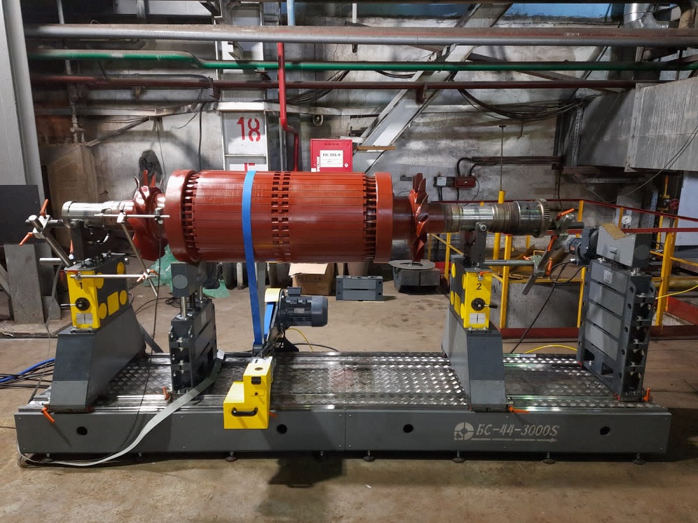
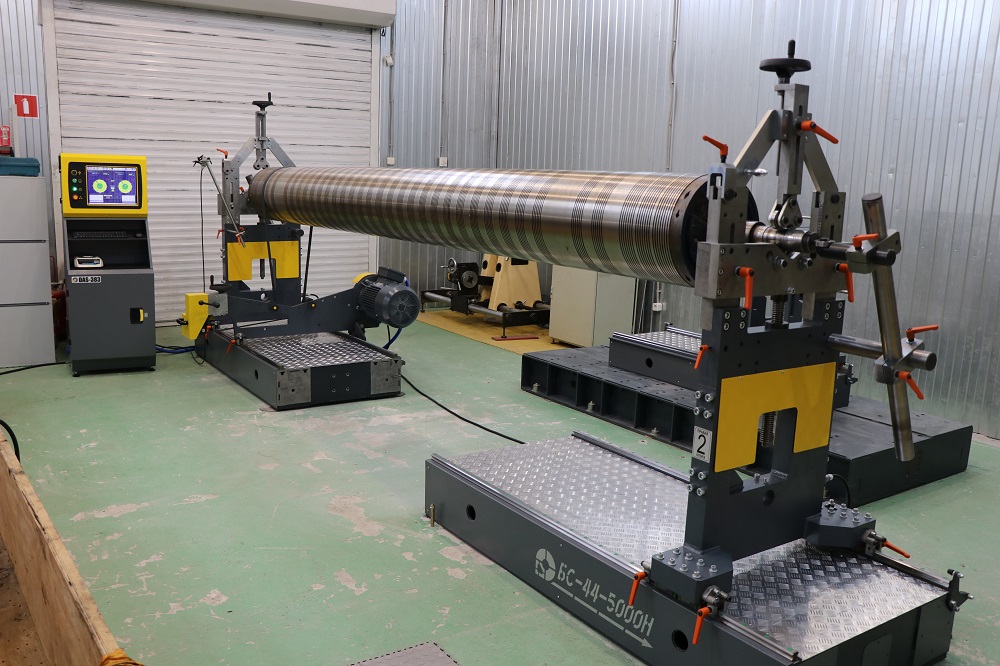
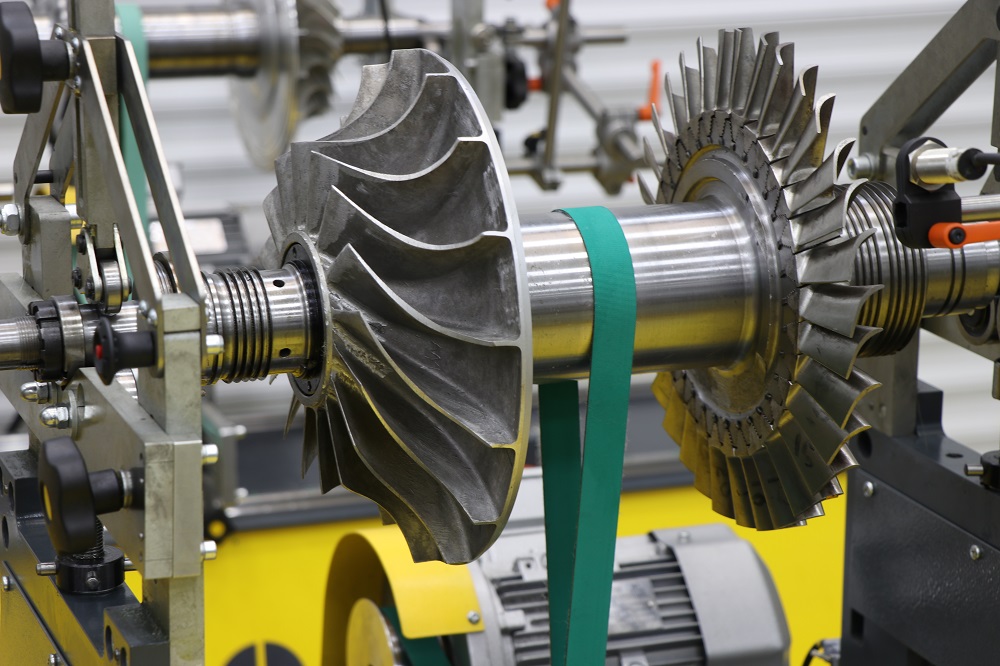
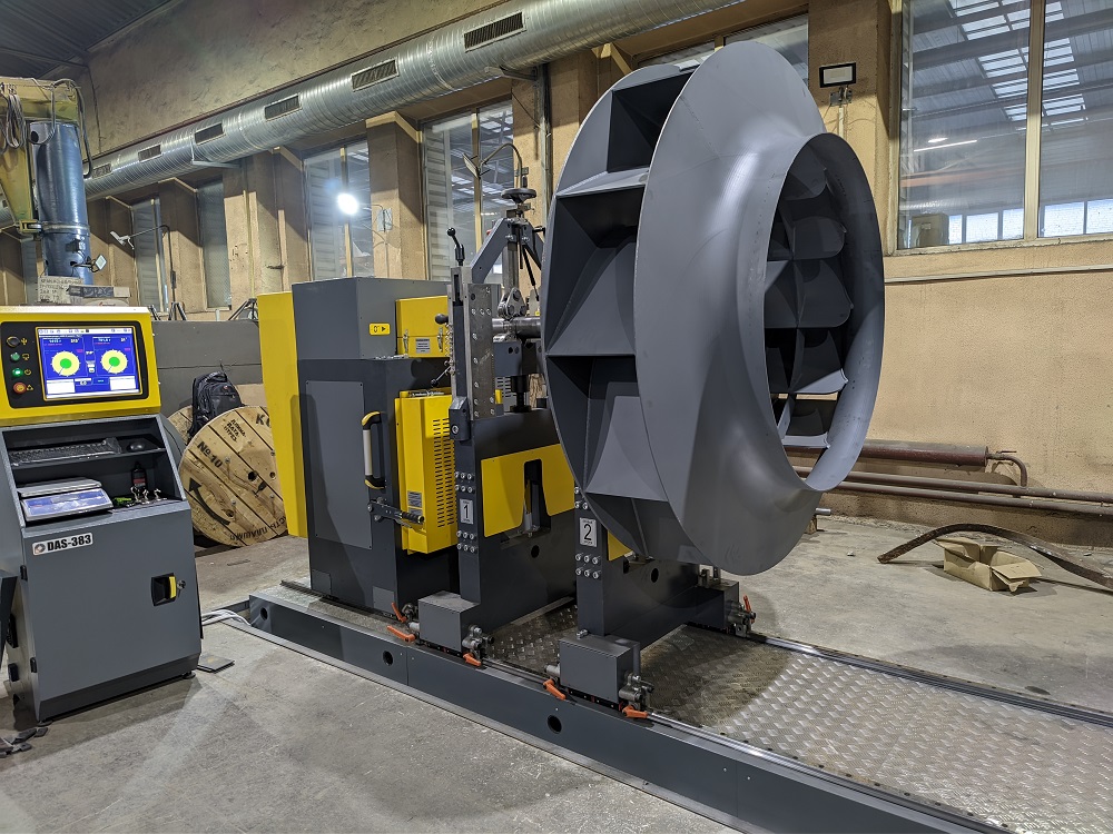
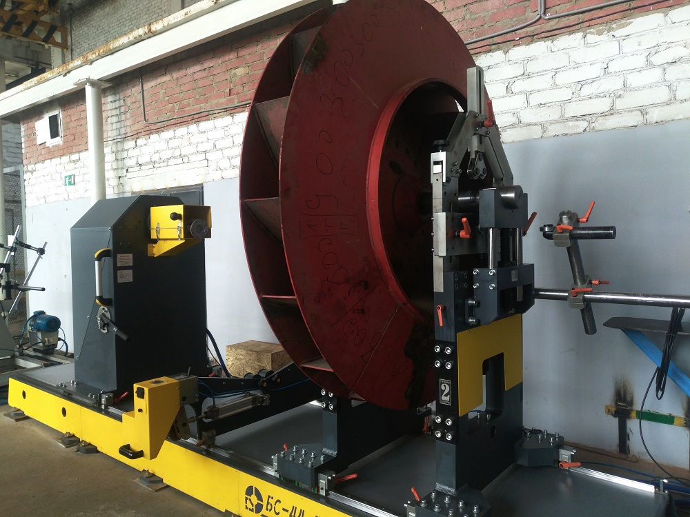
A universal horizontal-axis balancing machine designed for high-precision dynamic balancing of rotors such as components for compact engines, pumps, fans, turbines, electric motors, crankshafts, centrifuges, rollers and shafts, as well as almost any rotors, assemblies, and parts that meet the weight and size requirements.
Efficient and high-quality balancing is ensured by the advanced design, quality of construction, and modern computer signal processing algorithm. The machine has been in serial production for many years, is reliable, and maintainable.
Technical Specifications of the Balancing Machine
Application
Advantages
- Minimum achievable residual imbalance of 0.05 g*mm/kg.
- Imbalance reduction of up to 95% in a single run.
- Highest linearity of readings across all speed ranges and imbalance levels.
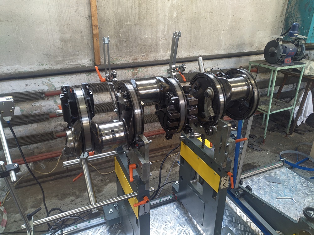
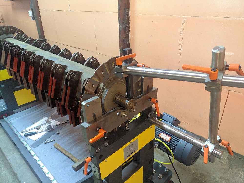
- Stands with 2 rolling blocks each, mounted on hardened and ground rail guides, providing more than a 12-fold safety margin while allowing easy manual movement of the stand without any tools or mechanisms.
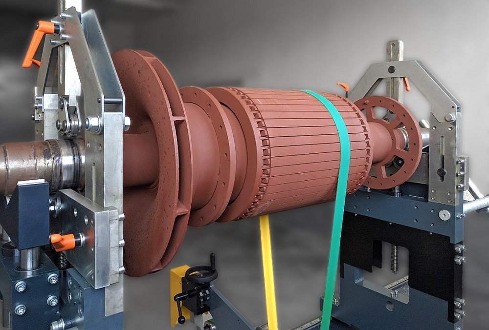
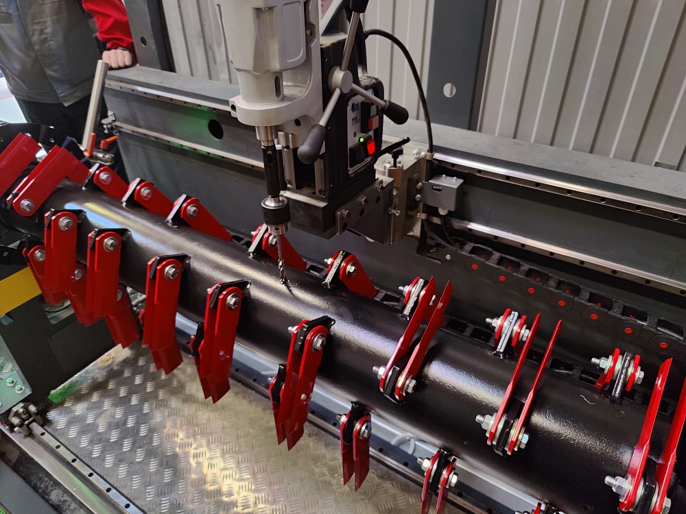
- Roller blocks feature V-shaped tooling, enabling the balancing of rotors in their own bearings.
- Special tooling for balancing rotors with a short distance between support journals.
- Air pressure adjustment, pressure gauge, and the belt tension system control lever are combined into a single unit.
- Record-fast changeover from one rotor size to another.
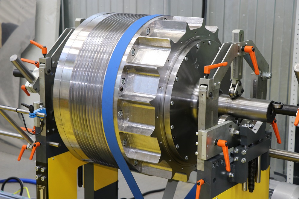
- Long-lasting support rollers with surface hardness of 60 HRC on SKF bearings.
- Ability to install machines on uneven, low-quality surfaces and freely move the machine, utilizing the "Machine to Rotor" approach.
Software
The "R-Bal V3.9" software, like the hardware, is developed by "PK Robals" LLC and is continuously improved. It features a simple, intuitive interface.
|
|
|
Rotor Balancing Window
Test Window
|
Graph of Vibration Amplitude and Phase vs. Rotation Speed 
Umar Test Sheet
|


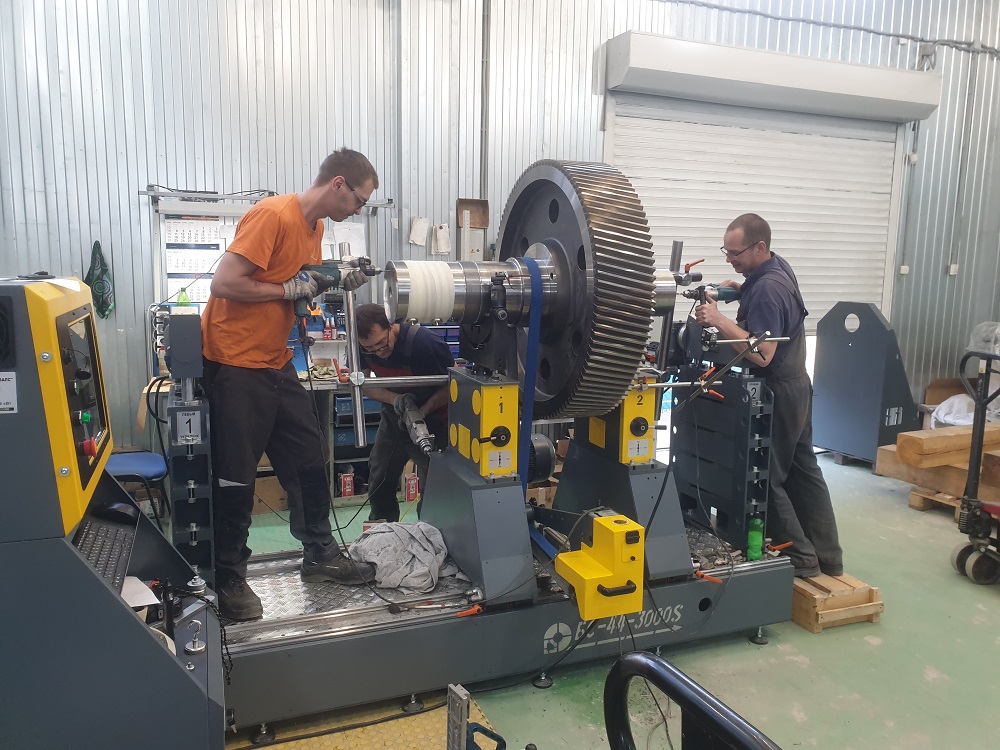
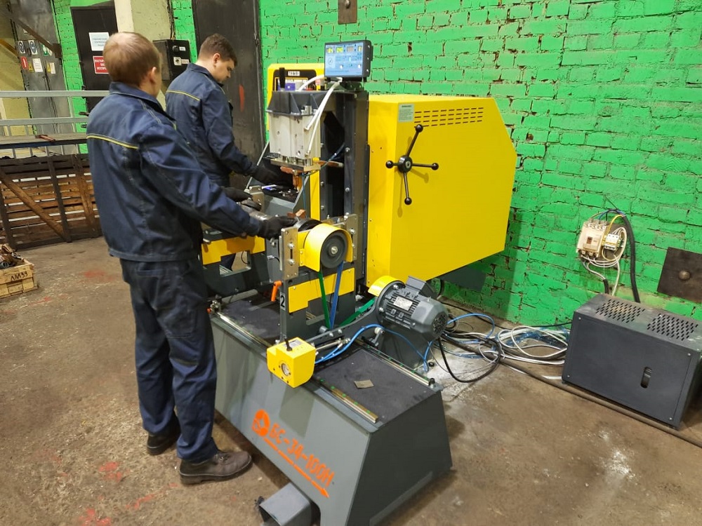
Launch and Dynamic Balancing Skills Training

When purchasing a balancing machine, we provide two types of commissioning services: an on-site visit by a commissioning engineer and remote machine startup.
A modern balancing machine is complex equipment, and in conditions of a shortage of qualified personnel, high-quality specialist training is especially important. Therefore, we provide assistance in personnel training. During the training of a balancing machine operator, skills for working with the machine and the principles of rotor dynamic balancing are transferred.
An excellent reference tool for the machine operator is the "Balance Guide: Multimedia Course for Preparation to Work on a Balancing Machine" program. The media course consists of a series of videos that provide a brief description of terms used in the balancing process, describe types of rotors, causes and types of imbalance, main correction methods, outline safety measures when working with the machine, principles of interaction with the machine components, and describe all the functions of the software that controls the balancing machine.
The program can be used to review knowledge acquired during the commissioning works.


